RS Headlight Door Wiring diagram (GM version)
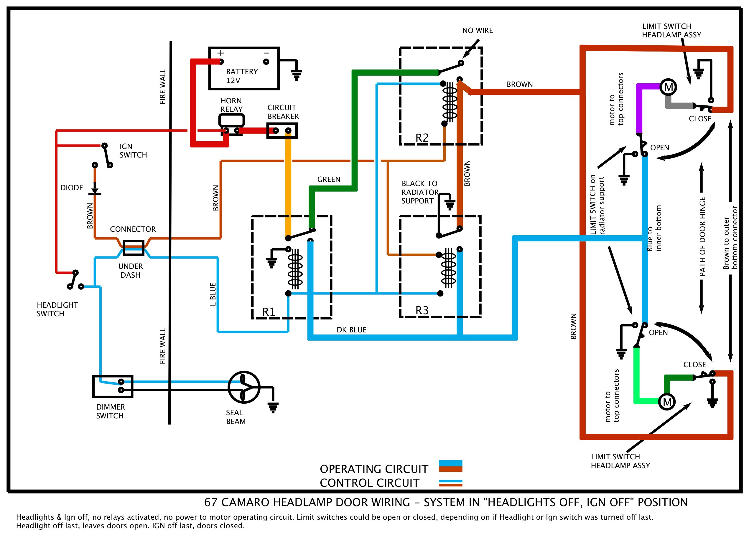
67 Camaro RS Headlight wiring diagram by David color
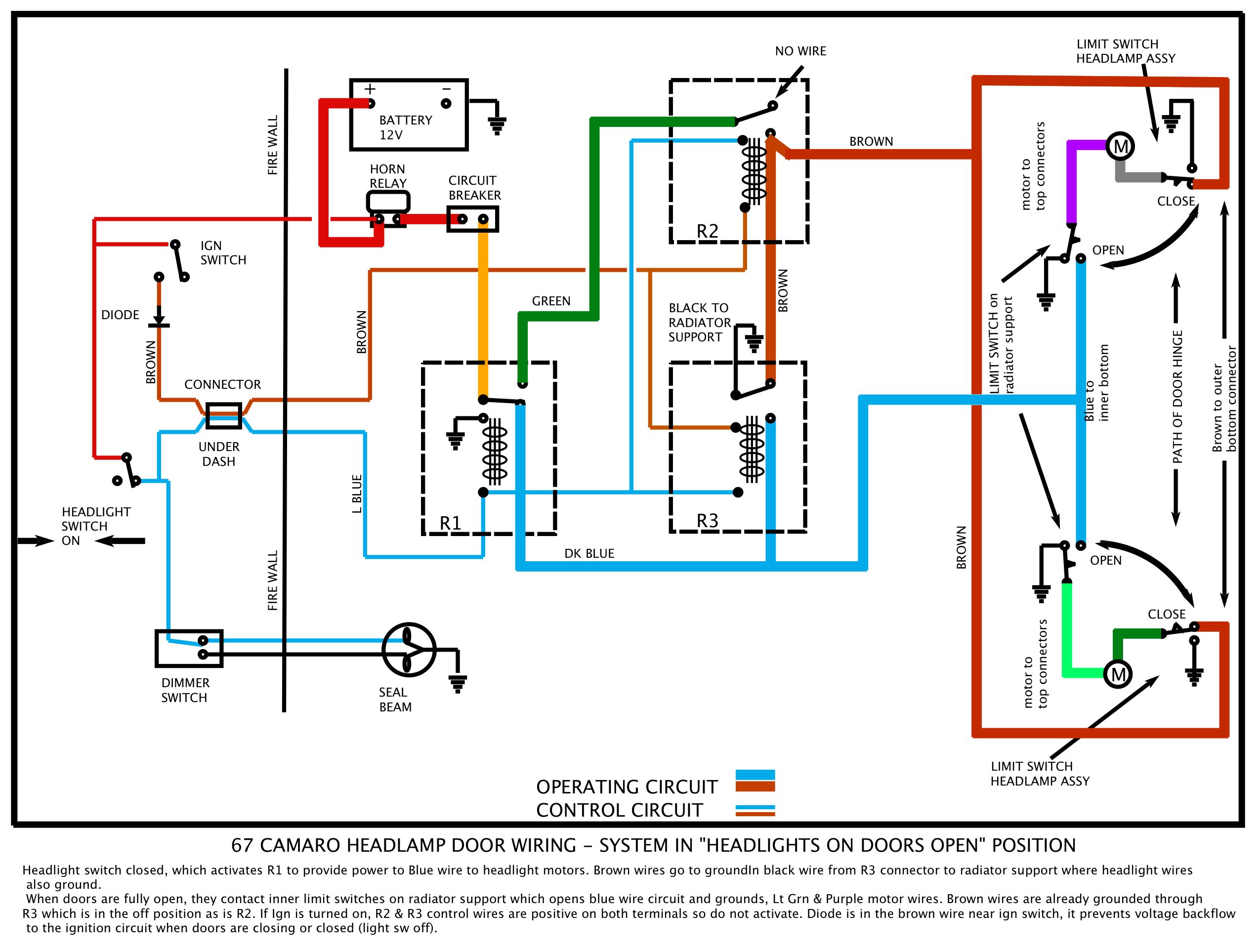
Headlights off, IGN on by David
Download link: .pdf of 69 GM Manual - RS wiring diagrams 67-68-69 with troubleshooting
A great .pdf from American Auto Wire on how the system works
More info on motor wiring here: http://www.retro-electro.net/FAQ.html
Retro Electro has a great replacement motor for this application.
Warning,
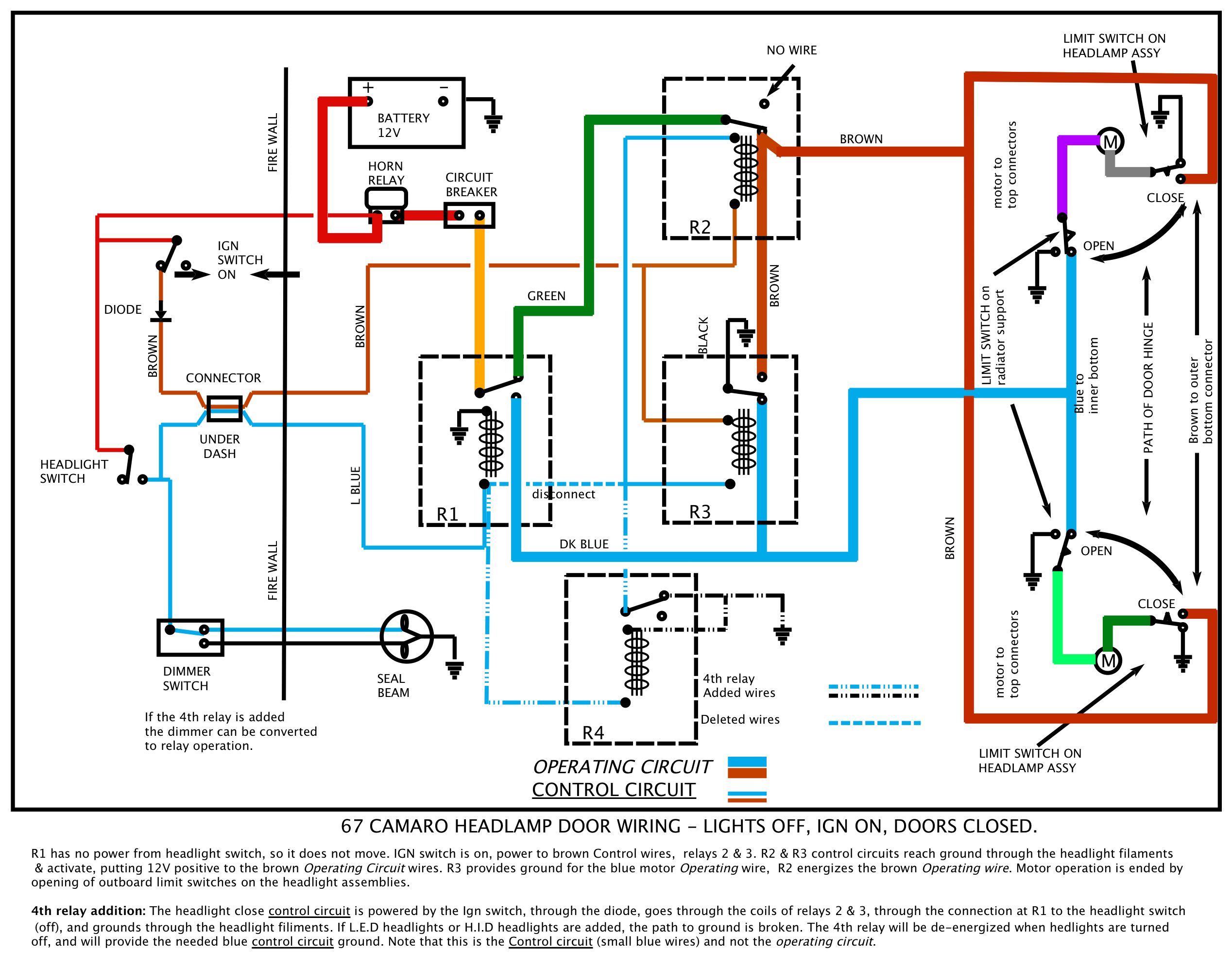
The door close circuit relies on ground through the headlight
filaments. Usually they are on low beam, but whatever the dimmer switch
has selected does it. If you convert to HID headlights then the ground
circuit may not exist or be enough. A fourth relay can be added to provide a ground path. Here is my drawing of how I think it should be wired. This is NOT TESTED YET!
One of the first things to check or do is replace the self-resetting circuit breaker on the relay board. That's the only part that has failed on my 67.
If the car has been sitting a long time, the motor output shafts can
rust and freeze them from turning. The rivets can be drilled out and
motor disassembled to free up the shafts and lube the gears with
grease. There are four stacks of gears inside, each stack is of a
different thickness, thin nearest the motor, thicker near the bottom.
Here are some notes on the stock system from Team Camaro member Lance.
"I thought I would add some additional info to suppliment the
diagram. The limit switches are obviously mounted on the radiator
frame and the headlight brackets. Unless yours is like mine was and
had the headlight switches missing and a bolt sheared off in the
hole, wires tied into the headlights, a broken wire hidden under a
connector at the relay board....enough of that, it's over and I
whipped it.
Back to what you need. The diagram posted will show all the major
wires. It doesn't show colors of the two wires which come from the
door motors. These plug into a harness that will hook into the limit
switches.
The driver's side radiator limit switch should have a grey wire
plugged into the top of it. The driver side limit switch on the
headlight should have a purple wire plugged into the top of it.
The passenger side radiator switch should have a DARK green wire
plugged into the top of it, while the headlight bracket switch should
have a LIGHT green wire plugged into the top of it. These wires and
plugs were present in my car but circumvented by an idiot wiring
scheme. They should be in yours also, if not disturbed.
Don't try turning on the headlights with just one limit switch
hooked up to test. The motor will run opposite and could cause damage
if allowed to run. The system only works when all wires are attached
to appropriate switches.
Your car may already have these in place but mine was butchered
and didn't. My lights work perfectly now.
BTW-- the diode is in the brown wire about 12 inches away from the
ignition in case you want to check it.
If the arms that actuate the doors are loose and won't turn the
doors properly, and the tightening nut is stripped like mine was,
post or email me and I'll tell you what I did."